Hakko T12 Compatible Soldering Iron Station Circuit Diagram
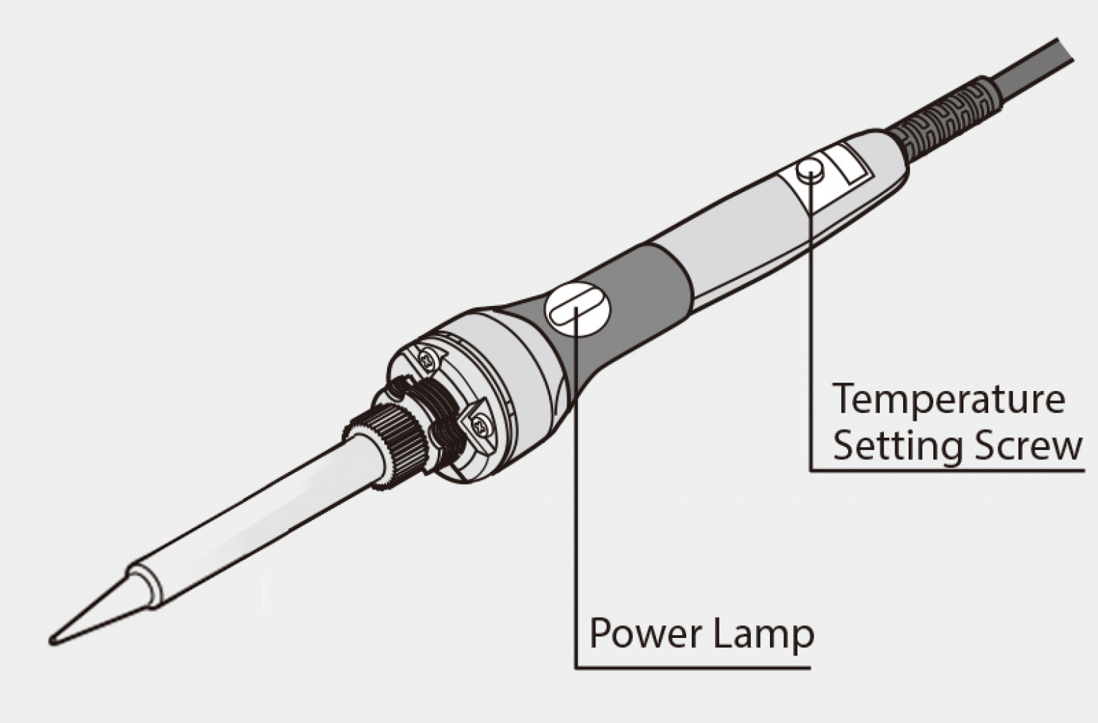
Hakko T12 Compatible Soldering Iron Station Circuit Diagram Use a temperature probe, preferably one designed especially for soldering irons, rather than guesswork, when making the adjustment. Note: VR4 should have a logarithmic taper to compensate for non-linearity in the temperature-resistance characteristic of the soldering iron.

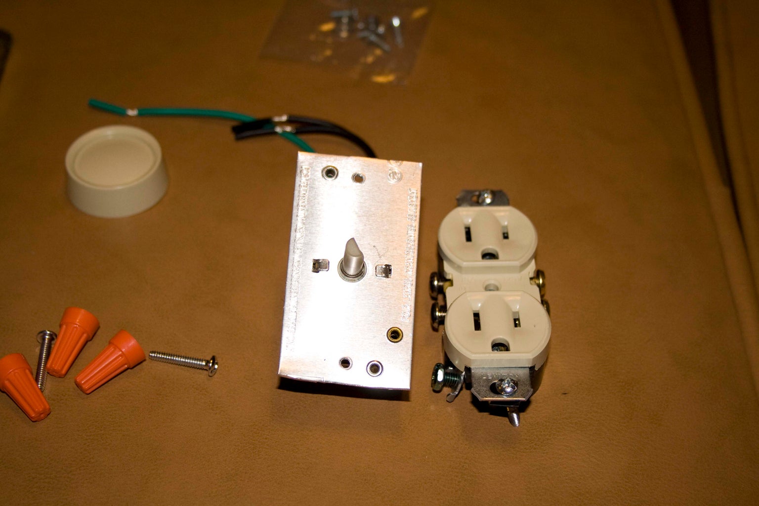
When soldering, sometimes the need arises to control the temperature of the soldering iron, especially, for micro soldering or any other precision soldering job. It is important to keep the temperature under control because overheating may damage sensitive semiconductor parts. That is where a temperature-controlled soldering station comes to The Soldering Iron, no longer plugs into the mains outlet. Remove the mains plug from your Soldering Iron. Connect the mains lead of your Soldering Iron to the Hot-Plate terminals of the PCB Temperature Controller. The cable from the K-Type Thermocouple connects the K-Type screw terminals. Be sure that the polarity is correct. Warning!
Controlled Soldering Iron Circuit Diagram
This post shows how to build a do it yourself 110 volt soldering station. It is a step by step guide that shows how to convert a regular plug-in soldering iron into a temperature controlled unit. It is an easy project that is inexpensive to make and requires only basic skills to build. It is…

By watching this video you can convert your ordinary Soldering Iron into Temperature Controllable Soldering Iron. If you have high power soldering iron and y
DIY 110v Temperature Controlled Soldering Station Circuit Diagram
PCB+Assembly from $2, Get JLCPCB Coupons:https://jlcpcb.com/HARGet SMT Coupons via Contacting JLCPCB FB: https://www.facebook.com/jlcpcb/Register now https: